
The following recommendations are intended to be a practical guide to ensure the safe and proper installation of cable ladder and cable tray systems and channel support and other support systems. These guidelines are not intended to cover all details or variations in cable ladder and cable tray installation and do not provide for every installation contingency.
It is recommended that the work described in the following section is carried out by competent persons who are familiar with the products being installed and the safety standards associated with them.
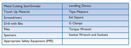
The following tools are commonly used for installation of cable management systems:
It is recommended that the work described in the following section is carried out by competent persons who are familiar with the products being installed and the safety standards associated with them.
2.1 Common tools for Installation
The following tools are commonly used for installation of cable management systems:
2.2 Structural characteristics
When considering the installation of the cable supports system it is imperative to avoid the cutting or drilling of structural building members without the approval of the project leader on site.
Cable ladders, cable trays and their supports should be strong enough to meet the load requirements of the cable management system including cables and any future cable additions and any other additional loads applied to the system.
Support systems can be broken down into a number of elements or components. To design a safe system it is necessary to check each element in turn to ensure:
• that it can safely support the loads being imposed upon it, and
• that the proposed fixings to adjacent components are also sufficient for the intended load and
• that any declared deflection limits are not exceeded
Consult the manufacturer for any further assistance on system design.
On many occasions cable ladder or cable tray is installed in circumstances where it will only ever carry a light cable load, possibly just one or two cables, and its main role is to physically secure and protect its contents. In these situations it is often the inherent ruggedness or the aesthetics of the cable ladder or cable tray design which bear most heavily on the specification decision. However, when a support system is required to be more heavily loaded it is useful to have knowledge of the theoretical aspects of rudimentary structural design in order to ensure that the completed system does fulfil its purpose with the greatest safety and economy.
2.2.1 Beams
Any installed cable ladder, cable tray or channel support system can be considered structurally as a loaded beam (Figures 2); four basic beam configurations may be found in a typical installation:
• Simply supported beam
• Fixed beam • Continuous beam
• Cantilever
2.2.1.1 Simply supported beam
A single length of cable ladder, cable tray or channel mounted on, but not restrained by two supports, represents a simply supported beam (Figure 2a), which will bend as any load is applied to it with the supports offering no restraint to this bending.
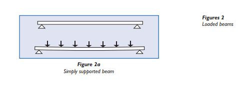
This simple beam arrangement is fairly onerous and does not realistically model many real life installations; thus the load/deflection information given in this guide is based upon more typical multi-span configurations, which also incorporate joints. However, if an un-jointed single span does actually occur the Safe Working Load can, as a practical guide, be taken as 0.5 of that indicated by the manufacturer’s multi-span loading details.
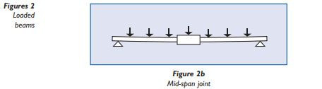
The introduction of a mid-span joint (Figure 2b) into a simple beam arrangement makes analysis far more complex. This arrangement represents the most testing situation for a cable ladder, cable tray or channel support joint. For this configuration the manufacturer should be consulted for the safe working load.
A fixed beam arrangement (Figure 2c) is a single structural member with both ends fastened rigidly to supports. Compared with a simple beam this degree of restraint does significantly increase the ability of the beam to carry loads but it is unlikely that cable ladder or cable tray can, in practice, be secured sufficiently rigidly to be considered as a fixed beam.
2.2.1.2 Fixed beam
A fixed beam arrangement (Figure 2c) is a single structural member with both ends fastened rigidly to supports. Compared with a simple beam this degree of restraint does significantly increase the ability of the beam to carry loads but it is unlikely that cable ladder or cable tray can, in practice, be secured sufficiently rigidly to be considered as a fixed beam.
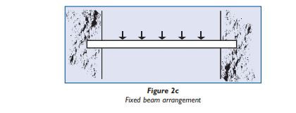
However, in the context of a complete cable ladder or cable tray system the main importance of the fixed beam configuration is that some appreciation of its properties, along with those of a simple beam arrangement, will assist the designer to understand the more complex behaviour of a continuous, multispan cable tray installation.
A typical multi-span cable ladder or cable tray installation behaves largely as a continuous beam and the greater the number of spans the closer the similarity. However in practice a run must contain joints and it can also never be considered of infinite length so it is important to appreciate how its characteristics do vary from span to span and how these variations should be taken into account when designing the installation.
2.2.1.3 Continuous beam
A typical multi-span cable ladder or cable tray installation behaves largely as a continuous beam and the greater the number of spans the closer the similarity. However in practice a run must contain joints and it can also never be considered of infinite length so it is important to appreciate how its characteristics do vary from span to span and how these variations should be taken into account when designing the installation.
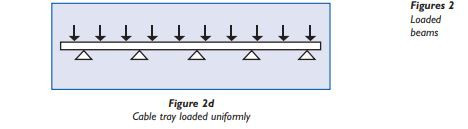
When a run of cable tray is loaded uniformly (Figure 2d) from end to end the load on each span is effectively in balance with the loads on the adjacent spans.
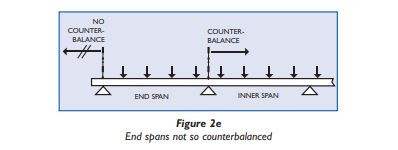
This causes the inner spans to behave substantially as fixed beams imparting to them a considerable load carrying ability. However the end spans (Figure 2e) of the installation are not so counterbalanced, thus they perform more akin to simple beams, with consequently lower load carrying capabilities.
Because of this it may be necessary to reduce the end span to less than the intermediate span length. The need for this depends on the ladder/tray manufacturer’s recommendations, which should be based on load tests carried out to BS EN 61537.
See section 2.4 Installation of straight cable ladder and cable tray lengths for further details.
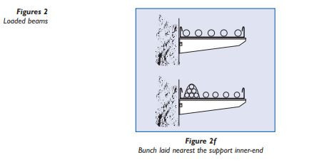
This type of arrangement most commonly occurs with the brackets which are used to support cable ladder or cable tray, these being fixed to the structure at one end only. For cable ladder or cable tray installations it is usual to consider the cable load to be uniformly distributed along the length of the cantilever arm (i.e. across the width of the ladder or tray); however, if cables will be bunched then their combined weight effectively acts as a point load on the arm so the bunch should be laid nearest the supported inner end (Figure 2f).
Consult manufacturers for safe working loads on cantilever arms. Manufacturers may supply safe working loads for both uniformly distributed loads and point loads at the ends of the cantilever arms.
Because of this it may be necessary to reduce the end span to less than the intermediate span length. The need for this depends on the ladder/tray manufacturer’s recommendations, which should be based on load tests carried out to BS EN 61537.
See section 2.4 Installation of straight cable ladder and cable tray lengths for further details.
2.2.1.4 Cantilever beam
This type of arrangement most commonly occurs with the brackets which are used to support cable ladder or cable tray, these being fixed to the structure at one end only. For cable ladder or cable tray installations it is usual to consider the cable load to be uniformly distributed along the length of the cantilever arm (i.e. across the width of the ladder or tray); however, if cables will be bunched then their combined weight effectively acts as a point load on the arm so the bunch should be laid nearest the supported inner end (Figure 2f).
Consult manufacturers for safe working loads on cantilever arms. Manufacturers may supply safe working loads for both uniformly distributed loads and point loads at the ends of the cantilever arms.
2.2.2 Columns
Any vertically orientated component, whether cable ladder, cable tray or support, acts structurally as a column; it is not usual to consider cable ladder or cable tray in this way because they are not designed for this purpose.
Supports are however, frequently used as vertical columns.
The downward load which can be applied to the end of a column is proportional to the column length and the compressive strength of the material from which it is made. However there are few real applications where no loads are applied from other directions and since the effects of such loads are very significant it is important to consider the totality of the intended structure rather than focus simply only on the loads applied down the column.
Proper structural analysis must take detailed account of any side forces or eccentric loads caused by cantilever arms or other brackets fixed to the vertical channel. Such calculations must be carried out by a competent person such as a structural engineer. Consult the manufacturer for safe loading data for supports used as columns.
2.2.3 Deflection
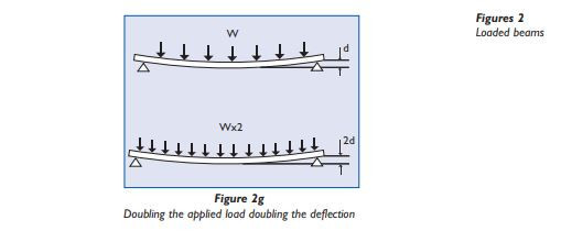
All beams will deflect (Figure 2g) when a load is imposed. The magnitude of the deflection depends upon the following factors:
• The load on the beam,
• The load type – UDL (uniformly distributed load) or point load,
• The distance between the beam supports (span),
• How the beam is fixed and supported,
• The size of the beam,
• The material of the beam.
A beam’s stiffness is derived from its cross sectional shape (defined by its ‘Moment of Inertia or ‘I’ Value’), and the stiffness of the material from which it is made (defined by its” Modulus of elasticity or ‘E’ value’). The greater the ‘I’ value of beam and the greater the ‘E’ value of its material, the greater the beam stiffness and the smaller the deflection when a load is imposed.
The deflection of a beam is proportional to the applied load. For example by doubling the applied load, the deflection will also be doubled (Figure 2g).
The position and type of load will also affect the amount of deflection on the beam. A Point Load will increase the deflection on a beam compared to a UDL of the same value. If designing a system with a point load at mid span, assume that the deflection will be doubled compared to the same load applied as a UDL.
If Deflection is an important factor, the easiest way to reduce it is to either; reduce the distance between the supports (the span), use a bigger section beam, or reduce the imposed loading.
Consult the manufacturer for details of deflections at their published safe working loads.
Deflection limits are usually expressed as a proportion of the support span (L) or the product width (W). In most UK steel construction, the allowable deflection at safe working load is L/200 for beams and L/180 for cantilevers, based on UK steel design standards.
Cable ladders, cable trays and their supports made to BS EN 61537 are allowed much greater deflections than this as listed below, so if deflections are important the manufacturer should be consulted to state what deflections occur at the safe working loads.
At the safe working load, the maximum allowable deflection along the length is L/100, and the maximum allowable deflection across the width is W/20, based on load test measurements.
At the safe working load the maximum allowable deflection is L/20, based on load test measurements.
At the safe working load the maximum allowable deflection is L/200 for beams & L/180 for cantilevers, based on calculations to UK steel design standards.
Where cable ladder and cable tray support systems are fixed to primary supports (e.g. structural steel work or elements of the building) it is important to ensure that the primary supports are strong enough to carry the imposed loads. This is generally the responsibility of the building designer and not the cable tray or cable ladder manufacturer.
The fixings used to connect the cable ladder and cable tray support systems to the primary supports also need to be checked to ensure that they are strong enough. This is normally the responsibility of the installer and/or the building designer.
The strut is usually formed from 1.5 mm or 2.5 mm thick steel and is generally available in either (41x41) mm or (41x21) mm profiles and with either a plain or a slotted base. Other sizes and profile combinations are available which are usually manufactured by welding strut sections together in different formats.
If Deflection is an important factor, the easiest way to reduce it is to either; reduce the distance between the supports (the span), use a bigger section beam, or reduce the imposed loading.
Consult the manufacturer for details of deflections at their published safe working loads.
Deflection limits
Deflection limits are usually expressed as a proportion of the support span (L) or the product width (W). In most UK steel construction, the allowable deflection at safe working load is L/200 for beams and L/180 for cantilevers, based on UK steel design standards.
Cable ladders, cable trays and their supports made to BS EN 61537 are allowed much greater deflections than this as listed below, so if deflections are important the manufacturer should be consulted to state what deflections occur at the safe working loads.
Cable ladder and cable tray made to BS EN 61537
At the safe working load, the maximum allowable deflection along the length is L/100, and the maximum allowable deflection across the width is W/20, based on load test measurements.
Supports: beams, hangers & cantilevers made to BS EN 61537
At the safe working load the maximum allowable deflection is L/20, based on load test measurements.
Supports: channel support systems made to BS 6946
At the safe working load the maximum allowable deflection is L/200 for beams & L/180 for cantilevers, based on calculations to UK steel design standards.
2.3 Support Systems
Where cable ladder and cable tray support systems are fixed to primary supports (e.g. structural steel work or elements of the building) it is important to ensure that the primary supports are strong enough to carry the imposed loads. This is generally the responsibility of the building designer and not the cable tray or cable ladder manufacturer.
The fixings used to connect the cable ladder and cable tray support systems to the primary supports also need to be checked to ensure that they are strong enough. This is normally the responsibility of the installer and/or the building designer.
2.3.1 Using channel to BS 6946
2.3.1.1 General
A Channel Support System (Figures 3) is a standardised system used in the construction and electrical industries for light structural support, often for supporting wiring, plumbing or mechanical components such as air conditioning or ventilation systems. The system usually consists of a steel channel section (strut), steel brackets, channel nuts and set screws (Figure 3a).
The strut is usually formed from 1.5 mm or 2.5 mm thick steel and is generally available in either (41x41) mm or (41x21) mm profiles and with either a plain or a slotted base. Other sizes and profile combinations are available which are usually manufactured by welding strut sections together in different formats.
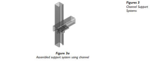
Systems can be assembled from strut, associated bracketry and fixings to produce: beams, columns, hangers, cantilevers and frames. Assembly details and a wide range of bracketry and sundries can be found in manufacturer’s catalogues.
The load carrying capabilities of the support system are based on a combination of calculations and load tests which are defined in BS 6946. This information should be published by the system manufacturer.
To maintain the system integrity it is essential that all the parts come from the same manufacturer and have been tested together as a system. The use of mixed parts from different manufacturers is potentially dangerous and may make void any product warranty.
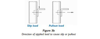
When a bracket is fixed to a channel using a channel nut and set screw, there are two safe working load values (slip and pull out) which should be quoted by the manufacturer (Figure 3b). To achieve the designated design slip and pull out ratings, all connections should be made using clean, dry components and tightened to the manufacturers stated torque value. Over tightened fixings could lead to damaged parts and reduced strength.
The load carrying capabilities of the support system are based on a combination of calculations and load tests which are defined in BS 6946. This information should be published by the system manufacturer.
To maintain the system integrity it is essential that all the parts come from the same manufacturer and have been tested together as a system. The use of mixed parts from different manufacturers is potentially dangerous and may make void any product warranty.
2.3.1.2 Channel nuts
When a bracket is fixed to a channel using a channel nut and set screw, there are two safe working load values (slip and pull out) which should be quoted by the manufacturer (Figure 3b). To achieve the designated design slip and pull out ratings, all connections should be made using clean, dry components and tightened to the manufacturers stated torque value. Over tightened fixings could lead to damaged parts and reduced strength.
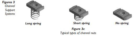
It must be emphasised that proper location and tightening of the channel nut within the channel is vital to the performance of the channel nuts (Figure 3c). A fastener that is not tightened to the manufacturers recommended torque will not consistently meet the manufacturers minimum published design loads.
2.3.1.3 Brackets
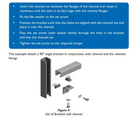
Framework brackets of all types are generally used to aid in the onsite fabrication of a support structure. Brackets (Figure 4) are available to cover most applications and are generally connected to channels in the following fashion:
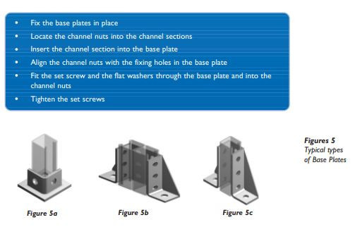
2.3.1.4 Base plates
Base plates (Figures 5) are generally used to fix vertical lengths of channel section to a firm floor and are generally connected to channels in the following fashion:
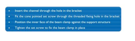
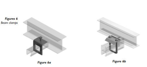
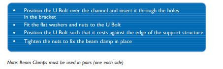
2.3.1.6 Beam clamps – ‘U’ bolt type
‘U’ bolt type beam clamps (Figure 6b) are generally used to fix lengths of channel section to existing supporting beams and are generally connecting channel to beam for heavier duty loads as shown:
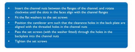
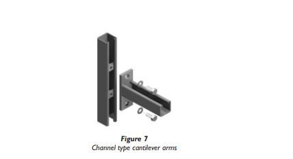
2.3.1.7 Channel type cantilever arms
Channel type cantilever arms (Figure 7) are generally used to provide support to services on a framework installation and are generally connected to channels in the following fashion:
2.3.1.8 Channel type trapeze hangers
Trapeze hangers (Figures 8) are suitable for use with cable ladder and cable tray, supported by threaded rods hung from ceiling brackets, channel support systems or from beam clamps attached to joists or steel beams.
When several levels of cable ladder or cable tray are mounted on the same threaded rods in a multiple level installation, it is important to ensure that the total load on any pair of rods does not exceed the safe working load of the rods or their attachment points.
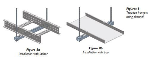
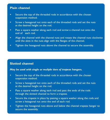
Assembly is generally carried out in the following order:
2.3.2 Supports not using channel to BS 6946
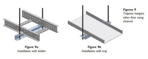
2.3.2.1 Trapeze hangers
Trapeze hangers (Figures 9) are suitable for use with cable ladder and cable tray, supported by threaded rods hung from ceiling brackets, channel support systems or from beam clamps attached to joists or steel beams.
When several levels of cable ladder or cable tray are mounted on the same threaded rods in a multiple level installation, it is important to ensure that the total load on any pair of rods does not exceed the safe working load of the rods or their attachment points.
Consult the manufacturer for specific details.
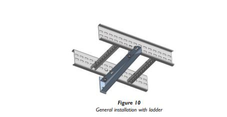
2.3.2.2 Cantilever arms
Cantilever arms enable horizontal runs of cable ladder or cable tray to be mounted to vertical steel, concrete or masonry surfaces or to channel support systems (Figure 10). Consult the manufacturer for specific details.
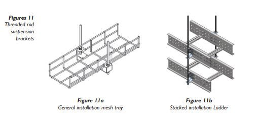
2.3.2.3 Threaded rod suspension brackets
Threaded rod suspension brackets (Figures 11) are useful when space is limited. When several levels of cable ladder or cable tray are mounted on the same threaded rods in a multiple level installation (Figure 11b), it is important to ensure that the total load on any pair of rods does not exceed the safe working load of the rods or their attachment points.
Consult the manufacturer for specific details.
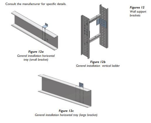
2.3.2.4 Wall support brackets
Wall support brackets (Figures 12) are an effective way of fixing any width of cable ladder or cable tray, running either vertically or horizontally, to a vertical support.
Consult the manufacturer for specific details.
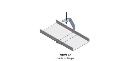
2.3.2.5 Overhead hangers
(Specific to cable tray)
Overhead hangers (Figure 13) enable tray to be supported from a single threaded rod giving easy access for laying cables from one side of the tray only.
Consult the manufacturer for specific details
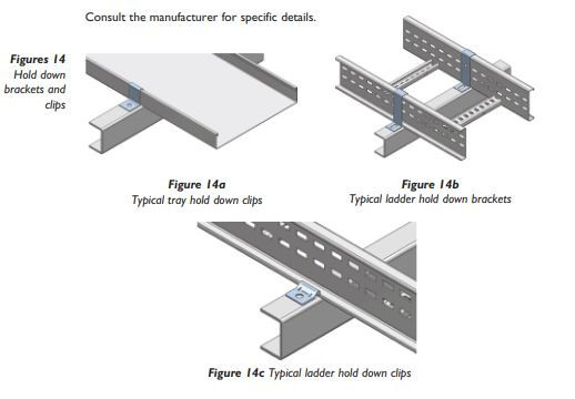
2.3.2.6 Hold down brackets and clips
Hold down brackets (Figures 14) and clips are used for securing cable ladder and cable tray to horizontal supports. If allowance for thermal expansion is required then the brackets and clips are generally not fixed to the cable ladder or cable tray.
Consult the manufacturer for specific details
2.3.2.7 Floor and Roof installations
Cable ladders or cable trays should not be laid directly onto the floor or roof of an installation. Cable ladders and cable trays should be mounted far enough off the floor or roof to allow the cables to exit through the bottom of the cable ladder or cable tray. If a channel support system is used for this purpose, mount the channel directly to the floor or roof and attached the cable ladder or cable tray to the channel using the fixings recommended by the manufacturer.
2.4 Straight cable ladder and cable tray lengths
2.4.1 Span size, joint positions and safe loadings
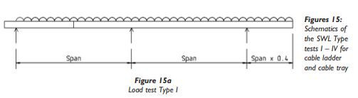
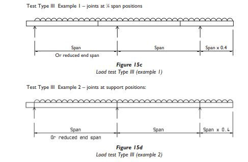
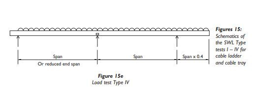
The standard BS EN 61537 states that manufacturers must publish SWL (safe working load) details for their products, and specifies load test methods for determining the SWLs which can be supported by cable ladder and cable tray. There are different types of load test (Figures 15), used dependant on what installation limitations the manufacturer specifies, with regard to span size, possibly with reduced end span size, and positions of joints.
The different test types and the installation conditions for which they are intended are as follows:
IEC load test Type I
Test with a joint in middle of the end span (Figure 15a). Simulates the worst case installation condition. Use for installations with joints anywhere.
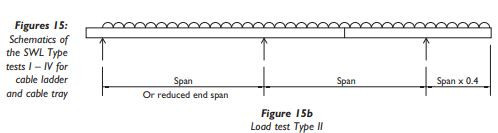
IEC load test Type II
Test with a joint in middle of the inner span (Figure 15b), with an optional reduced end span as the manufacturers recommendation.
Simulates an installation condition with span/joint limitations. Use for installations with no joints in the end spans, with reduced end span as the manufacturer’s recommendation.
IEC load test Type III
Test with joints at manufacturers recommended positions (Figures 15c and 15d), with an optional reduced end span as the manufacturer’s recommendation.
Simulates an installation condition with span/joint limitations. Use for installations with joints at manufacturers recommended positions, with reduced end span as the manufacturer’s recommendation.
Test Type III Example 1 – joints at 1 ⁄4 span positions:
IEC load test Type IV
A variation on test types I or II, used for products which have a localised weakness in the side member.
The test is identical to test types I & II, but repositioned slightly so that the side member weakness is directly above the middle support.
Use for installations as type I or type II above as appropriate.
It is important when using manufacturers loading data to check what test type has been used to produce the SWL data, and hence what installation limitations may apply, particularly with regard to joint positions & end span size.
For calculation of loadings on a cable ladder or cable tray installation, it is important to include all dead loadings and any imposed loadings such as wind, snow and ice.
See section 3.4 for more details.
2.4.2 Straight lengths installation
After the supports are in place, the installation of the cable ladder or cable tray can begin at any convenient location. It is not necessary to begin at one end of the run in all cases. It is ideal if circumstances permit to lay out the system so that joints fall in the desired positions as this will visually aid installation and also maximise the system rigidity.
To begin the installation, place a straight length across two supports so that the ends of the length are not directly on the support. If the support span is equal to or greater than the length of the straight lengths then bolt two lengths together for this step.
Place the next straight length across the next support and attach it to the previous length with a pair of coupler plates and relevant fixings with the bolt heads on the inside of the cable ladder or cable tray unless otherwise specified by the manufacturer.
2.4.3 Installation of longer spans
Manufacturer’s published data should be consulted in order to ascertain the maximum span that a product can be used with, and any special provisions required for long spans. Special provisions may be required particularly if used externally where there may be dynamic loadings such as wind & snow; e.g. wider supports, extra supports or bracing, limitations on joint positions.
2.5 Coupler types (refer to manufacturer’s literature)
Couplers are used to join together two separate components, whether that may be lengths, fittings or a combination of both. Couplers are supplied in pairs or individually.
2.5.1 Straight coupler
Straight couplers are used for joining together straight lengths and or fittings.
2.5.2 Fitting to fitting coupler
Depending on the manufacturer fitting to fitting couplers are used for joining together cable ladder fittings (bends, tees, risers etc).
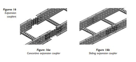
2.5.3 Flexible expansion coupler
Flexible expansion couplers (Figures 16) can be used to:
- provide a semi-flexible joint where straight cable ladder or cable tray runs span separate structures between which some relative movement is possible.
- make provision for changes in the length of a straight cable ladder or cable tray runs due to thermal expansion or contraction.
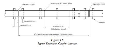
2.5.3.1 Distance between expansion joints
The distance between expansion joints (Figure 17) should be calculated by the following formula.
D = E/(KT)
Where D = distance between expansion joints (m) E = allowable movement for each expansion joint (m) T = temperature range [Maximum temperature – minimum temperature] (ºC) K = coefficient of linear expansion of the material (ºC-1)
Typical values for K
• Mild steel 13 x10-6
• Stainless steel grade 1.4404 (316) 16 x10-6
• GRP Variable (consult manufacturer)
• PVC 55 x10-6
2.5.3.2 Example calculation using a typical sliding type expansion coupler
Mild steel cable ladder, with K = 13 x 10-6 °C-1
Allowable movement at each expansion joint E = 28 mm = 0.028 m
Temperature range of installation T = -15 ºC to +35 ºC = 50 ºC
Maximum distance ‘D’ between expansion joints
D=E/(KT) =0.028/(13 x 10-6 x 50) = 43 m
For ease of installation an expansion coupler should be fitted every 14th length of 3m ladder giving 42m between expansion couplers.
Method for determining the installation gap for sliding type expansion couplers.
Using the graph (Figure 18) below:
• Mark the maximum seasonal temperature on line A
• Mark the minimum seasonal temperature on line B
• Draw a diagonal line C between the two marked points on line A and B
• Draw line D horizontally at the temperature the cable ladder or cable tray is to be installed at.
• A vertical line E should then be constructed from the intersection of the diagonal line C and the horizontal line D
• The installed gap setting can read off the base of the graph (F).
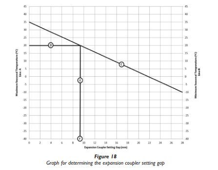
Note the gap setting will vary depending on the manufacturers design. The example above is for a coupler with a total 28 mm expansion range.
Mild steel cable ladder, with K = 13 x 10-6 °C-1
Allowable movement at each expansion joint E = ±10 mm = ± 0.01 m
Temperature range of installation T = -20 °C to +40 °C = 60 °C
Maximum distance ‘D’ between expansion joints
D = E/(KT) = 0.01/(13 x 10-6 x 60) = 12.8 m
For ease of installation an expansion coupler should be fitted every 4th length of 3m ladder giving 12 m between expansion couplers.
As the temperature at the time of installation is unknown the expansion movement of the coupler (in this example) would range from + 10 mm to – 10 mm depending on the temperature at the time of installation. The value of ‘E’ therefore used for the calculation is half of the total range of movement of the coupler.
NOTE at expansion joint positions supports should be no more than 600 mm either side of the joint, unless special strong expansion couplers are available that allow supports to be positioned greater than 600 mm from the joint.
2.5.3.3 Example calculation using a typical concertina type expansion coupler
Mild steel cable ladder, with K = 13 x 10-6 °C-1
Allowable movement at each expansion joint E = ±10 mm = ± 0.01 m
Temperature range of installation T = -20 °C to +40 °C = 60 °C
Maximum distance ‘D’ between expansion joints
D = E/(KT) = 0.01/(13 x 10-6 x 60) = 12.8 m
For ease of installation an expansion coupler should be fitted every 4th length of 3m ladder giving 12 m between expansion couplers.
As the temperature at the time of installation is unknown the expansion movement of the coupler (in this example) would range from + 10 mm to – 10 mm depending on the temperature at the time of installation. The value of ‘E’ therefore used for the calculation is half of the total range of movement of the coupler.
NOTE at expansion joint positions supports should be no more than 600 mm either side of the joint, unless special strong expansion couplers are available that allow supports to be positioned greater than 600 mm from the joint.
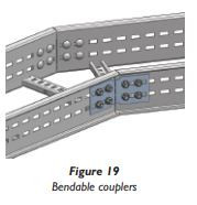
2.5.4 Horizontal Adjustable/Bendable coupler
Bendable couplers (Figure 19) can be used for:
• Fabricating fittings on site from cut lengths of cable ladder.
• Correcting minor misalignment problems
• Coupling lengths of cable ladder to form articulated bends
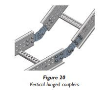
2.5.5 Vertical hinged coupler
Vertical hinged couplers (Figure 20) can be used for:
• Fabricating fittings on site from cut lengths of cable ladder.
• Solving minor vertical misalignment problems.
• Coupling articulated risers to adjacent cable ladders.
• Forming risers at non-standard angles.
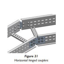
2.5.6 Horizontal hinged coupler
Horizontal hinged couplers (Figure 21) can be used for:
• Fabricating fittings on site from cut lengths of cable ladder.
• Solving minor horizontal misalignment problems.
• Forming horizontal bends at non-standard angles.
2.7 Fittings
Fittings are best described as factory fabricated items which facilitate a change of direction and / or width and provide intersections between straight cable ladder or cable tray runs. A standard range of fittings would include such items as a flat bend, inside or outside riser, equal or unequal tee, 4-way crossover & reducer. Other fittings may also be available and consultation with the manufacturer may be necessary. In cable management installations fittings must always be provided with local support.
2.7.1 Radius of cable ladder and cable tray fittings
The radius for cable ladder and cable tray fittings is usually determined by the bending radius and stiffness of the cables installed on the cable ladder or cable tray. Typically the cable manufacturer will recommend a minimum bend allowance for each type of cable. The radius of the cable ladder or cable tray fitting should be equal to or larger than the minimum bending radius of the largest cable installed.
2.7.3 Fittings without integral coupler
Fittings without integral couplers are normally joined together and/or to straight lengths using couplers as used with straight lengths.
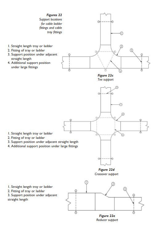
2.7.4 Support locations for cable ladder and cable tray fittings
Where fittings are used, supports are usually required under the adjacent straight lengths close to the fitting joints (Figures 22).
Additional supports are sometimes required directly underneath large fittings (see key item 4 in the relevant figures below).
Consult manufacturers’ published data for details of the maximum distance between supports & fitting joints, and for which size fittings require additional supports.

2.8 Accessories
An accessory is a component used for supplementary function such as cable retention, covers and dividers etc.
2.8.1 Dividers
Dividers are used to physically separate different types or groups of cable within one cable ladder or cable tray run. The divider is usually manufactured from the same material as the cable ladder or cable tray onto which it is installed. Dividers should be installed prior to the cable being laid and then fastened using the fixings recommended by the manufacturer.
2.8.2 Covers
Covers provide mechanical and environmental protection for cables being carried by cable ladder or cable tray, can be closed or ventilated and should be fitted in accordance with the manufacturer’s instructions.
2.9 Site modification
2.9.1 General
No installation will be perfect and at sometime it may become necessary to cut the cable ladder or cable tray during installation. Care must be taken to ensure that all modifications made on site to cable ladder or cable tray are performed by competent personnel only.
2.9.2 Repair of damaged surfaces
Cable ladders or cable trays that have been hot dip galvanized after manufacture will need to be repaired after cutting, drilling and de-burring. Cutting operations leave bare metal edges that will begin to corrode immediately. Cable ladder and cable tray made from mill galvanized steels do not need to be repaired because they are not designed to be used in heavily corrosive atmospheres and have bare metal edges inherent in their design.
Repairing a galvanized finish must be done in accordance with BS EN ISO 1461 usually using a zinc rich paint. Other protective coatings that are cut or damaged must be repaired with compatible coatings.
2.10 Earth protection and EMC
2.10.1 Protection of cables
Cable ladder and cable tray systems are designed to provide continuous support to any cables installed upon them. Due to the fact that cable ladders and cable trays are never really fully enclosed they do not offer complete mechanical and environmental protection. For this reason unsheathed, single insulated power cables should not be installed on cable ladder and cable tray. Cable installed on cable ladder and cable tray should have some form of mechanical protection in the form of PVC sheathing, steel wire armouring or a copper covering (MICC).
Where moisture may be present, copper covered cables must also be PVC Sheathed to avoid electrochemical corrosion between the copper and a metallic cable support system.
2.10.2 Electrical continuity
Cables mounted on metal cable ladder and cable tray systems will normally be equivalent to either a Class I construction (e.g. mineral insulated cables without an overall PVC covering) or a Class II equivalent construction (e.g. PVC insulated and sheathed cable). Therefore, a metal cable ladder and cable tray system need not be purposely earthed unless used as a protective conductor, BS 7671 Regulation 543.2.1 refers.
Unless the metal cable ladder and cable tray system is liable to introduce a potential that does not already exist in the location, (generally earth potential) it will not meet the definition of an extraneous- conductive-part. Therefore, it would normally not be required to be connected to either a protective bonding conductor or any supplementary bonding conductor.
When required, metal cable ladder and cable tray systems should have adequate electrical continuity to ensure equipotential bonding and connections to earth. Manufacturers are required by BS EN 61537 to declare whether or not their systems are classified as having electrical continuity characteristics.
Installations shall comply with the requirements of BS 7671 (The Wiring Regulations).
2.10.3 EMC
Cable ladder and cable tray systems on their own are passive in respect of electromagnetic influences. The installation of current carrying cable however, may cause electromagnetic emissions that may influence information technology cables. As a guide for the installation of IT cables it is recommended that BS EN 50174-2 is consulted
Continue reading: Installation of cable